Three-way valves provide for variable flow through the coil while maintaining somewhat constant flow in the system.
Mixing and diverting three-way valves are shown in Figures 1. In a mixing valve, two incoming streams are combined into one outgoing stream. In a diverting valve, the opposite takes place. The exiting port of the mixing valve and the entering port on the diverting valve are called the common port, typically labeled C (for common), or sometimes AB.
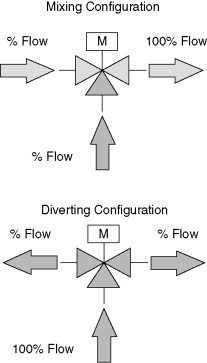
Figure 1. Mixing (Left) and Diverting (Right) Valve Configurations
In Figure 2, the bottom port of the mixing valve is shown as normally open to the common port, COM. (open to the common when the stem is up).
Figure 2. Three-way Mixing Valve
This port is typically labeled NO (for normally open), although it is sometimes labeled B (bottom port). The other port is normally closed to the common and is typically labeled NC (normally closed), although it is sometimes labeled A or U (upper port). The common outlet is usually labeled COM or OUT. The diverting valve is similarly labeled.
In Figure 3, the common port of the diverting valve is shown in the same location as that on the mixing valve, on the side.
Figure 3. Three-way Diverting Valve
With some manufacturers, the valve may be designed so that the common port is the bottom port, with water exiting left and right. Notice that, like two-way valves, the plugs for both mixing and diverting valves are arranged to avoid water hammer (i.e., flow is under the valve seat). Therefore, it is important that the valve be properly piped and tagged with respect to flow direction, and a mixing valve must not be used for diverting service, or vice versa.
Mixing valves are less expensive than diverting valves and thus are more common. In most cases, where three-way valves are desired, they are arranged in the mixing configuration, but occasionally a diverting valve is required.
The more common use of mixing valves over diverting valves is apparently the reason why two-way valves are traditionally placed on the return side of coils (where a mixing valve must go) rather than on the supply side (where a diverting valve would be). From a functional perspective, it makes no difference on which side of the coil the two-way valve is located. Two-way valves located on the return side of coil piping will maintain pump discharge pressure on hydronic coils to enable positive air venting from the coil return header. Additionally, the fluid passing through the valve on the return side is tempered by the heat loss/gain through the coil.
Figure 4 shows two typical three-way mixing valve schematics.
Figure 4. Typical Three-way Mixing Valve Arrangements
Notice how the valve ports are labeled; it is important that control schematics be labeled in this manner to be sure the valve is piped in the desired configuration so that it will fail to the proper position and respond properly to the control action of the controller. The common port is oriented so that flow always returns to the distribution return. In the example at the top of Figure 4, the valve is normally closed to flow through the coil. If the normally open arrangement was desired, the port labels on the schematic could simply be reversed (the NO label would be shown at the valve return). However, because the normally open port on a real three-way mixing valve is on the bottom, simply relabeling the schematic encourages errors in the field. It is better to rearrange the schematic, as shown on the bottom of Figure 4, so that the NO port is shown in the proper position.
Notice the balancing valve shown in the coil bypass line of Figure 4. While not generally a part of the control system (and, as such, it is not typically shown on control schematics), this valve is nevertheless essential for proper operation of the water distribution system unless the coil pressure drop is very low. The valve must be balanced to match the pressure drop of the coil so that when the valve is in the bypass position, the pressure drop will be similar to the path through the coil. Without the valve, a fluid short-circuit occurs and the supply-to-return differential pressure in the system will drop, possibly starving other coils in the system that require a higher differential pressure.
Plugs in three-way valves are available in the same styles as two-way valves, typically linear and equal percentage. However, not all manufacturers make both styles in all sizes, so the designer does not always have flexibility in selection within one manufacturer’s line. In some rare instances, valves are built with two different plug styles, allowing the valve to behave in a linear fashion for one port and an equal percentage fashion for the other. Diverting valves seem to be available primarily with equal percentage plugs. The selection of plug style is discussed in the next section.
While three-way valves are most commonly used where constant fluid flow is desired, in reality they will not result in constant flow no matter which plug style is selected. As noted above, the balancing valve can be used to ensure that the flow is the same when flow goes 100% through either the coil or the bypass. However, when the valve is in between these two extremes, flow will always increase with a linear plug and, to a lesser extent, with an equal percentage plug. The reason for this will become apparent when we consider how valves are sized and selected in the next section.
Before selecting and sizing there is one more behavioral characteristic of modulating valves for us to consider. Modulating control valves have an inherent operating characteristic called “range ability factor.” The range ability factor of a control valve is the ratio of the maximum flow to the minimum controllable flow. This characteristic is measured under laboratory conditions with a constant differential applied to the valve only. A range ability factor of 10:1 indicates that the valve alone can control to a minimum flow of 10%.
The installed ability of the same valve to control to low flows is the “turn down ratio.” In the real system, the pressure across the valve does not stay constant. Typically, as the valve closes the differential pressure across the valve rises. The ratio of the differential pressure drop when the valve is fully open to when it is almost closed is called its “authority.” If the pressure were to stay the same the authority would be P/P = 1. However, if the pressure quadrupled the authority would be ¼ = 0.25. The valve turn down ratio is calculated by multiplying the inherent range ability factor times the square root of the valve authority. Hence, a valve that has decent range ability (say 20:1) but poor authority (say 0.2) will not have good capability to control down to low flows (range ability 20•√0.2 = 9:1), and may only be able to provide “‘on-off” control over a good part of its flow range.
Many globe style HVAC control valves do not have high range ability factors; a major manufacturer lists values from 6.5:1 to 25:1 for their range of globe valves from ½ inch to 6 inch. Most characterized ball control valves, however, have very high range ability factor (usually > 150:1).
- Key Data Tables on Three-Way Control Valves
- Table 1: Three-Way Valve Types and Configurations
- Table 2: Three-Way Valve Port Labeling
- Table 3: Valve Plug Types and Characteristics
- Table 4: Performance Characteristics of Control Valves
- Table 5: Installation Considerations
- Table 6: Flow Behavior with Three-Way Valves
Key Data Tables on Three-Way Control Valves
As an engineer focusing on HVAC systems, you’ll find these consolidated data tables valuable for understanding three-way control valve applications, configurations, and performance characteristics.
Table 1: Three-Way Valve Types and Configurations
| Valve Type | Flow Configuration | Common Port Location | Application |
|---|---|---|---|
| Mixing Valve | Two incoming streams combine into one outgoing stream | Side port (labeled COM, C, or AB) | Most common, used on return side of coil |
| Diverting Valve | One incoming stream divides into two outgoing streams | Side port (labeled COM, C, or AB) | Less common, more expensive, used on supply side |
Table 2: Three-Way Valve Port Labeling
| Port | Mixing Valve | Diverting Valve | Alternative Labels |
|---|---|---|---|
| Common | Outlet | Inlet | COM, C, AB |
| Normally Open | Bottom port | Bottom port | NO, B (Bottom) |
| Normally Closed | Upper port | Upper port | NC, A, U (Upper) |
Table 3: Valve Plug Types and Characteristics
| Plug Style | Flow Characteristic | Applications | Notes |
|---|---|---|---|
| Linear | Flow directly proportional to stem position | Simple applications, high pressure drop | Less common in three-way valves |
| Equal Percentage | Flow increases exponentially with stem position | Most HVAC applications | Most common, especially in diverting valves |
| Dual Style | Different plug styles in each port | Specialized applications | Rare availability |
Table 4: Performance Characteristics of Control Valves
| Characteristic | Definition | Typical Range | Importance |
|---|---|---|---|
| Range Ability Factor | Max flow : Min controllable flow ratio | 6.5:1 to 25:1 (globe valves) ≥150:1 (characterized ball valves) |
Indicates inherent control capability |
| Authority | Δp(valve open) : Δp(valve nearly closed) | 0.2 to 1.0 | Higher values provide better control |
| Turn Down Ratio | Range ability factor × √Authority | Varies by installation | Actual controllable flow range in system |
Table 5: Installation Considerations
| Consideration | Requirement | Purpose | Impact if Ignored |
|---|---|---|---|
| Flow Direction | Must follow manufacturer specifications | Prevents water hammer | Valve damage, noise, poor control |
| Balancing Valve | Required in bypass line | Matches coil pressure drop | Flow short-circuit, starving other coils |
| Orientation | Must match schematics | Ensures proper fail position | Improper system response |
Table 6: Flow Behavior with Three-Way Valves
| Plug Type | Flow Behavior at Mid-Position | System Impact |
|---|---|---|
| Linear | Flow increases above design | Higher energy use, potential pumping issues |
| Equal Percentage | Flow increases slightly | Better system stability, preferred for most applications |
| Any Type | Cannot maintain perfect constant flow | Requires proper balancing for closest approximation |


