The control valve is possibly the most important component of a fluid distribution system because it regulates the flow of fluid to the process under control. In HVAC systems, control valves are primarily used to control the flow of chilled water, hot water, and condenser water, the subject of this section. Control of other fluids including steam, refrigerants, gasses, and oil are similar in many aspects but are not specifically addressed here because they have specific requirements for design including issues of safety and material compatibility.
Styles and Principles of Operation
Control valves may be either two-way (one pipe in and one pipe out) which act as a variable resistance to flow or three-way (two pipes in and one out for mixing valves – one pipe in and two out for diverting valves) as depicted in Figure 1. Three-way valves may be either mixing (two flow streams are merged into one) or diverting (a single flow stream is broken into two), as shown in the figure. With all three configurations shown, the valves modulate flow through the cooling or heating coil to vary the capacity of the coil.
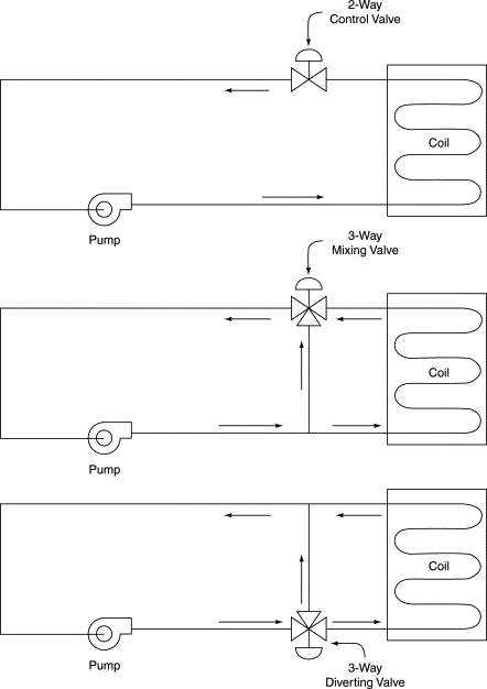
Figure 1.Simple Two-way and Three-way Valve Circuits
With the two-way configuration, flow through the circulation system is variable. In the three-way configurations, flow remains relatively constant through the loop which includes the pump and varies in the loop containing the coil. This works well for systems in which the supply of heat, typically a boiler, or supply of cooling, typically a chiller, requires a constant flow. In other systems, it may be that constant flow in the coil is important, perhaps to prevent freezing. In this case the pump can be in the coil loop.
Control valves typically come in three valve styles: globe, butterfly, and ball. The globe-type valve has been the most common for many years, but the characterized ball valves are becoming very popular and are starting to become a significant part of the working marketplace. Below 2-inch size, they have usually sweat (soldered) or screwed connections, while above 2 inch they are typically flanged.
Figure 2 shows a typical globe-type two-way single-seated control valve. It consists of a body, a single seat, and a plug. The plug is connected to a stem, which, in turn, is connected to the actuator, also called the actuator or motor. Moving the stem up and down controls the flow. Full shut-off is achieved when the plug is firmly down against the seat.

Figure 2. Two-way Globe Single-seated Valve (Fluid Flow is Left to Right)
The body is connected to the piping system in any suitable way (screwed, flanged, welded, soldered, etc.), but it is important that unions or something similar be provided so that the valve can easily be removed for repair or replacement. Make sure the flow direction is correct with the arrow on the valve body. Service (manual) valves should be provided to isolate individual control valves or piping subsystems.
An actuator that is sprung to lift the valve stem upon power loss combined with the globe valve shown in Figure 2 would produce a normally open valve assembly. The valve is open when power is removed from the actuator.
Figure 3 shows a globe valve that closes with the stem up. Using this actuator with the valve in Figure 3-3 would produce a normally closed valve assembly as the valve is closed when power is removed from the actuator. In both cases, the stem must be driven against the flow of fluid to close the valve. Normally open valves are generally desired, when available, as they always fail to the open position, and, if closure is desired, then manual valves can be closed down/off to restrict the flow until repairs can be made.

Figure 3. Normally Closed Globe Two-way Valve
The figures indicate that flow through the valve must occur in the direction shown by the arrow. All control valves will have an arrow cast into the outside of the body to indicate flow direction. The reason for this is as follows: in any linkage between motor and valve stem there will be some slack, a little free movement of the valve stem. When flow occurs in the correct direction, the velocity pressure of the fluid and the fluid differential pressure across the valve will tend to open the valve. Therefore, the motor must press tightly to close it, taking up any free movement. If flow takes place in the wrong direction, the velocity pressure tends to close the valve (pushing down on top of the plug of the valve in Figure 2). When the valve throttles toward its closed position, the pressure may be enough to push the plug to the closed position, taking advantage of the free movement or slack in the valve stem. When this happens, flow ceases, then the velocity pressure component disappears, and free movement allows the valve to crack open. Flow begins, the velocity component reappears, and the cycle is repeated indefinitely. Each time the flow stops and starts, the inertial force of the fluid in the pipe causes a shock known as water hammer. Besides being noisy and annoying, it can cause failure of the piping system. Therefore, it is important never to install a control valve backward.
Figure 4 shows a double-seated valve, also called a balanced valve. As the name implies, it has two plugs and seats arranged so that fluid differential pressure is balanced and the actuator does not have to fight against differential pressure to close the valve, as it does in the single-seated valves shown in the Figure 2. This reduces the size of the actuator. But the valve inherently cannot provide tight shut-off. This reduces its applicability to HVAC systems, where tight shut-off is usually desired, to minimize energy costs (to prevent leakage and simultaneous heating and cooling).
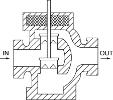
Figure 4. Double-seated Two-way Globe Valve
Modulating globe-type control valves is made with two basic types of plugs: the linear (V-port) plug (see Figure 5) and equal percentage plug (see Figure 6). Many manufacturers have variations on these two designs (called modified linear or modified equal percentage), the characteristics of which are usually similar to those described here.
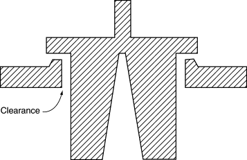
Figure 5. Linear (V-Port) Valve Plug
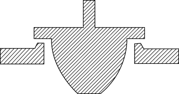
Figure 6. Equal Percentage Valve Plug
A flat plate plug (see Figure 7) is sometimes used for two-position, quick-opening duty.
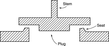
Figure 7. Quick-opening (Flat Plate) Valve Plug
The graph in Figure 8 shows the relationship of percent flow to percent plug lift for each plug type, assuming constant pressure drop across the valve. Plug lift is defined as zero with the valve closed, and up to 100% when the valve is opened to the point beyond which no increase in flow occurs. The flat plate plug provides about 60% of full flow when open only 20%. Thus, it is suitable only for two-position control.
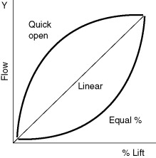
Figure 8. Control Valve Characteristics
Control valve characteristics is a complex study of the what characteristics are needed from the HVAC system and its coil, and how the valve is designed to operate and function. Correctly choosing these characteristics issues can yield a properly combined control valve for its application. A very simple example of this is depicted in Figure 9.
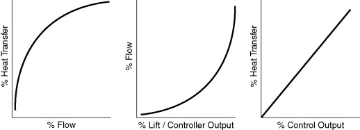
Figure 9. Combination of Coil and Control Valve Characteristics
As shown in Figure 10, the linear plug has an essentially linear characteristic while the equal percentage plug is shaped so that the flow increment is an exponential function of the lift increment. This means that when the valve is almost closed, a large percent change of lift is required for a small change of flow.
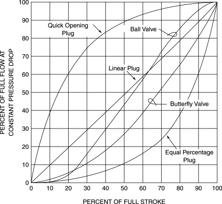
Figure 10. Typical Valve Characteristics at Constant Pressure Drop
As the plug reaches its last tiny increment of closure until it fully shuts, the flow drops off very quickly. This minimum flow rate just before closure is a function of the physical construction of the valve, plug, and seat. The ratio of the minimum rate to maximum rate at the same pressure drop across the valve is called the range ability or turn-down ratio. For a typical HVAC control valve, this ratio will be about 20:1, which is equivalent to a 5% flow when the valve is barely cracked open. This is usually adequate for HVAC control work. Valves with larger ratios are available but they are more expensive.
Figure 11 shows a butterfly valve, which is basically a round disk that rotates within the valve body to modulate flow. While not always suitable for modulating duty (as discussed in the next section), butterfly valves can be used for shut-off, balancing, and two-position and three-way duty. The butterfly valve has a characteristic that falls in between the equal percentage and linear plug characteristics, see Figure 10, while the ball valve has a nearly linear characteristic. Different flow characteristics are desired in different applications.
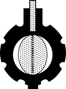
Figure 11. Butterfly Valve
A ball valve (basically a bored ball which rotates in the valve body) is shown in Figures 12 and 13. Ball valves are primarily used as shut-off and balancing valves on small piping systems (2 inch nominal pipe size and less), but recently they have been adapted for automatic control applications, primarily for small coils such as reheat coils. Ball valves, without an appropriate plug, should not be used in large flow control purposes; typically the resistance, when open, is too low and it lends itself to allowing a much smaller size valve in relation to the pipe, and its control is unstable.
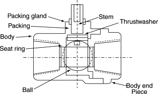
Figure 12. Ball Valve Layout
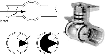
Figure 13. Characterized Ball Valve
Ball valves with a “characterized plug” can be used in some typical HVAC control applications as depicted in Figure 13.
The flow characteristics of these ball valve standard and characterized plugs are shown in Figure 14.
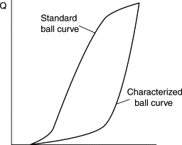
Figure 14. Ball Valve
The three types of valves considered – globe, butterfly, and ball – all need driving with an actuator. The globe valve actuator moves the valve stem in and out as shown in Figure 15. The actuators for ball and butterfly valves must rotate the valve stem with an actuator typically as shown in Figure 16.

Figure 15. Valve Actuators – Move Stem Up and Down
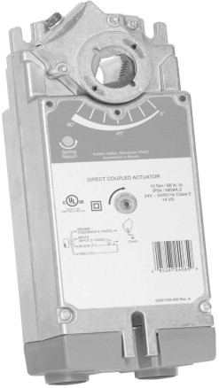
Figure 16. Valve Actuator – Rotary (Courtesy Honeywell)
Using two-way valves offers several advantages over three-way valves, including:
-
The valve is less expensive to buy and install. This is partly offset by the actuators typically costing more because of the higher differential pressure across the valve.
-
Two-way valves result in variable flow that will reduce pumping energy. This is particularly true when variable speed drives are used on pumps.
-
Piping heat losses as well as pump energy can be reduced by using the valve to shut-off flow to inactive coils while serving active coils; this is an advantage when a central plant serves many coils operating on different schedules.
-
Diversity in load may be taken into account when sizing the pumping and distribution systems, potentially reducing their costs.
-
The need for system balancing flows is reduced or eliminated in most applications. Because the valves will only use as much chilled or hot water as required by the load, the two-way valve system is self-balancing under normal operating conditions. With three-way valves, flow occurs through the circuit at all times (either through the coil or the bypass), so flow must be balanced to ensure that the required flow is delivered to each coil.
On the other hand, the use of two-way valves can have disadvantages:
-
Some chillers and boilers cannot handle widely varying flow rates. Using three-way valves in place of two-way valves is one way to resolve this problem. (Two-way valves may still be used at coils, but some other means to maintain flow through the equipment must be included, such as a pressure actuated bypass, VSD, or a primary/secondary pumping system. The reader is referred to the ASHRAE Handbook – HVAC Systems and Equipment and other sources for more information on these alternative designs.)
-
Two-way valves cause differential pressures to increase across control valves, particularly when pumps are uncontrolled . This reduces the controllability of the system and may even cause valves to be forced open by the water pressure. Actuators typically are sized larger to handle the much larger pressure close-offs.
-
Because of the advantages they offer, use of two-way valves is generally recommended, used with the appropriate bypass or VSD design, particularly for large systems where their energy and first-cost advantages are significant. But the system design and valve selection (discussed in the next section) must be able to mitigate these two disadvantages for the system to work successfully.


