制御バルブは、制御下のプロセスへの流体の流れを調整するため、おそらく流体分配システムの最も重要なコンポーネントです。 HVAC システムでは、制御バルブは主に冷水、温水、およびこのセクションの主題である凝縮水の流れを制御するために使用されます。蒸気、冷媒、ガス、油などの他の流体の制御も多くの点で似ていますが、安全性や材料の適合性の問題など、設計に特有の要件があるため、ここでは特に取り上げません。
運用のスタイルと原則
Control valves may be either two-way (one pipe in and one pipe out) which act as a variable resistance to flow or three-way (two pipes in and one out for mixing valves – one pipe in and two out for diverting valves) as depicted in 図1. Three-way valves may be either mixing (two flow streams are merged into one) or diverting (a single flow stream is broken into two), as shown in the figure. With all three configurations shown, the valves modulate flow through the cooling or heating coil to vary the capacity of the coil.
図 1.二方弁、三方弁の簡易回路
2 方向構成により、循環システム内の流量が変化します。 3 方向構成では、ポンプを含むループ内の流れは比較的一定のままですが、コイルを含むループ内では変化します。これは、熱の供給 (通常はボイラー)、または冷却の供給 (通常はチラー) が一定の流量を必要とするシステムに適しています。他のシステムでは、おそらく凍結を防ぐために、コイル内の一定の流れが重要である可能性があります。この場合、ポンプはコイルループ内にある可能性があります。
Control valves typically come in three valve styles: globe, butterfly, and ball. The globe-type valve has been the most common for many years, but the characterized ball valves are becoming very popular and are starting to become a significant part of the working marketplace. Below 2-inch size, they have usually sweat (soldered) or screwed connections, while above 2 inch they are typically flanged.
図2に、典型的なグローブ型二方単座制御弁を示します。本体、シングルシート、プラグで構成されます。プラグはステムに接続され、ステムはアクチュエーター (アクチュエーターまたはモーターとも呼ばれます) に接続されます。ステムを上下に動かすことで流れを制御します。プラグがシートにしっかりと下にあると、完全に遮断されます。

図2. Two-way Globe Single-seated Valve (Fluid Flow is Left to Right)
The body is connected to the piping system in any suitable way (screwed, flanged, welded, soldered, etc.), but it is important that unions or something similar be provided so that the valve can easily be removed for repair or replacement. Make sure the flow direction is correct with the arrow on the valve body. Service (manual) valves should be provided to isolate individual control valves or piping subsystems.
電力損失時にバルブ ステムを持ち上げるためにバネがかかるアクチュエータと、図に示すグローブ バルブを組み合わせたもの図2通常開いているバルブアセンブリが生成されます。アクチュエータから電源が遮断されると、バルブが開きます。
図3は、ステムを上げた状態で閉じるグローブ バルブを示しています。バルブを取り付けた状態でこのアクチュエータを使用する図 3-3アクチュエータから電力が除去されるとバルブが閉じられるため、常閉バルブアセンブリが生成されます。どちらの場合も、バルブを閉じるには、流体の流れに逆らってステムを駆動する必要があります。常開バルブは常に開位置にならないため、利用可能な場合は通常、常開バルブが望ましいです。また、閉じたい場合は、手動バルブを閉じたりオフにして、修理が可能になるまで流れを制限することができます。

図3。常閉グローブ二方弁
図は、バルブを通る流れが矢印で示された方向に発生する必要があることを示しています。すべてのコントロールバルブには矢印が投げられます。outside of the body to indicate flow direction. The reason for this is as follows: in any linkage between motor and valve stem there will be some slack, a little free movement of the valve stem. When flow occurs in the correct direction, the velocity pressure of the fluid and the fluid differential pressure across the valve will tend to open the valve. Therefore, the motor must press tightly to close it, taking up any free movement. If flow takes place in the wrong direction, the velocity pressure tends to close the valve (pushing down on top of the plug of the valve in 図2)。バルブが閉位置に向かって絞られると、バルブステムの自由な動きやたるみを利用して、圧力がプラグを閉位置に押すのに十分な場合があります。これが起こると、流れが止まり、速度圧力成分がなくなり、自由に動くことでバルブが開くようになります。流れが始まり、速度成分が再び現れ、このサイクルが無限に繰り返されます。流れが停止したり開始したりするたびに、パイプ内の流体の慣性力によって「衝撃」が発生します。ウォーターハンマー。騒音や不快感を伴うだけでなく、配管システムの故障を引き起こす可能性があります。したがって、コントロールバルブを逆に取り付けないことが重要です。
図4は、バランス バルブとも呼ばれる複座バルブを示しています。名前が示すように、流体の差圧のバランスがとれるように配置された 2 つのプラグとシートがあり、図に示す単座バルブのようにアクチュエータがバルブを閉じるために差圧と戦う必要がありません。図2. This reduces the size of the actuator. But the valve inherently cannot provide tight shut-off. This reduces its applicability to HVAC systems, where tight shut-off is usually desired, to minimize energy costs (to prevent leakage and simultaneous heating and cooling).
図4。複座二方グローブバルブ
Modulating globe-type control valves is made with two basic types of plugs: the linear (V-port) plug (see 図5) and equal percentage plug (see 図6). Many manufacturers have variations on these two designs (called modified linear or modified equal percentage), the characteristics of which are usually similar to those described here.
図5. Linear (V-Port) Valve Plug
図6. イコールパーセンテージバルブプラグ
A flat plate plug (see 図7) は、2 位置のクイックオープン任務に使用される場合があります。
図7. Quick-opening (Flat Plate) Valve Plug
のグラフ図 8は、バルブ全体の圧力降下が一定であると仮定した場合の、各プラグ タイプの流量パーセントとプラグ リフトパーセントの関係を示しています。プラグリフトは、バルブが閉じている状態ではゼロとして定義され、流量の増加が起こらない点までバルブが開いている場合は最大 100% と定義されます。平板プラグは、20% だけ開いたときに全流量の約 60% を提供します。したがって、2 位置制御のみに適しています。
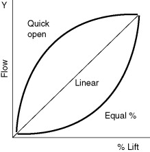
図 8。コントロールバルブの特性
制御バルブの特性は、HVAC システムとそのコイルにどのような特性が必要か、またバルブがどのように動作および機能するように設計されているかについての複雑な研究です。これらの特性問題を正しく選択すると、用途に合わせて適切に組み合わせられた制御バルブが得られます。この非常に単純な例を次に示します。図9.
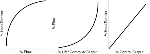
図9。コイルとコントロールバルブの特性の組み合わせ
に示すように図10、リニア プラグは本質的に線形の特性を持ちますが、イコール パーセンテージ プラグは流量の増分が揚力の増分の指数関数となるような形状になっています。これは、バルブがほぼ閉じている場合、わずかな流量変化に対して大きなリフト変化率が必要であることを意味します。
図10。一定の圧力損失における典型的なバルブ特性
プラグが完全に閉じるまでの最後のわずかな閉鎖段階に達すると、流れは非常に急速に低下します。閉じる直前のこの最小流量は、バルブ、プラグ、およびシートの物理的構造の関数です。バルブ全体の同じ圧力降下における最小速度と最大速度の比は、レンジ能力またはターンダウン比と呼ばれます。一般的な HVAC 制御バルブの場合、この比率は約 20:1 になります。これは、バルブがかろうじて開いたときの 5% の流量に相当します。通常、HVAC 制御作業にはこれで十分です。より大きな比のバルブも入手可能ですが、より高価になります。
図11 shows a butterfly valve, which is basically a round disk that rotates within the valve body to modulate flow. While not always suitable for modulating duty (as discussed in the next section), butterfly valves can be used for shut-off, balancing, and two-position and three-way duty. The butterfly valve has a characteristic that falls in between the equal percentage and linear plug characteristics, see 図10、ボールバルブはほぼ線形の特性を持っています。用途に応じて、異なる流量特性が求められます。
図11. バタフライバルブ
A ball valve (basically a bored ball which rotates in the valve body) is shown in 図12 と 13. Ball valves are primarily used as shut-off and balancing valves on small piping systems (2 inch nominal pipe size and less), but recently they have been adapted for automatic control applications, primarily for small coils such as reheat coils. Ball valves, without an appropriate plug, should not be used in large flow control purposes; typically the resistance, when open, is too low and it lends itself to allowing a much smaller size valve in relation to the pipe, and its control is unstable.
図12. ボールバルブのレイアウト
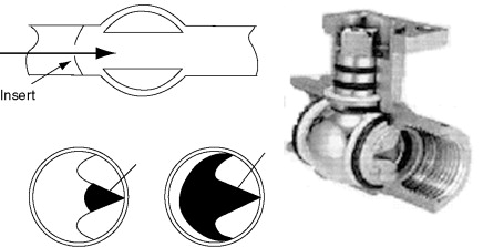
図13. 特性ボールバルブ
「特性プラグ」を備えたボール バルブは、図に示すように、いくつかの典型的な HVAC 制御アプリケーションで使用できます。図13.
これらのボールバルブの標準プラグと特性プラグの流量特性を以下に示します。図14.
図14. ボールバルブ
検討した 3 種類のバルブ (グローブ、バタフライ、ボール) はすべてアクチュエーターで駆動する必要があります。グローブ バルブ アクチュエータは、図に示すようにバルブ ステムを内外に動かします。図15。ボール バルブおよびバタフライ バルブのアクチュエータは、通常、図に示すように、アクチュエータを使用してバルブ ステムを回転させる必要があります。図16.

図15。バルブアクチュエーター – ステムを上下に移動
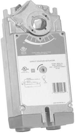
図16. Valve Actuator – Rotary (Courtesy Honeywell)
二方バルブを使用すると、三方バルブに比べて次のようないくつかの利点があります。
-
バルブの購入と設置が安価になります。これは、バルブ前後の差圧がより高いため、一般にコストが高くなるアクチュエータによって部分的に相殺されます。
-
二方バルブにより流量が変化し、ポンピングエネルギーが低減されます。これは、可変速ドライブがポンプで使用されている場合に特に当てはまります。
-
バルブを使用してアクティブなコイルに供給しながら非アクティブなコイルへの流れを遮断することで、配管の熱損失とポンプのエネルギーを削減できます。これは、中央プラントが異なるスケジュールで動作する多数のコイルにサービスを提供する場合に有利です。
-
ポンプおよび分配システムのサイズを決定する際に負荷の多様性を考慮することができ、コストを削減できる可能性があります。
-
The need for system balancing flows is reduced or eliminated in most applications. Because the valves will only use as much chilled or hot water as required by the load, the two-way valve system is self-balancing under normal operating conditions. With three-way valves, flow occurs through the circuit at all times (either through the coil or the bypass), so flow must be balanced to ensure that the required flow is delivered to each coil.
一方、二方バルブの使用には次のような欠点がある可能性があります。
-
Some chillers and boilers cannot handle widely varying flow rates. Using three-way valves in place of two-way valves is one way to resolve this problem. (Two-way valves may still be used at coils, but some other means to maintain flow through the equipment must be included, such as a pressure actuated bypass, VSD, or a primary/secondary pumping system. The reader is referred to the ASHRAE ハンドブック – HVAC システムおよび機器これらの代替デザインの詳細については、その他の情報源を参照してください。)
-
二方弁により、特にポンプが制御されていない場合、制御弁間の差圧が増加します。これによりシステムの制御性が低下し、水圧によってバルブが強制的に開く可能性もあります。アクチュエータは通常、はるかに大きな圧力閉鎖に対応できるように、より大きなサイズになっています。
-
Because of the advantages they offer, use of two-way valves is generally recommended, used with the appropriate bypass or VSD design, particularly for large systems where their energy and first-cost advantages are significant. But the system design and valve selection (discussed in the next section) must be able to mitigate these two disadvantages for the system to work successfully.


